Context and Details
(tl;dr – scroll to the images)
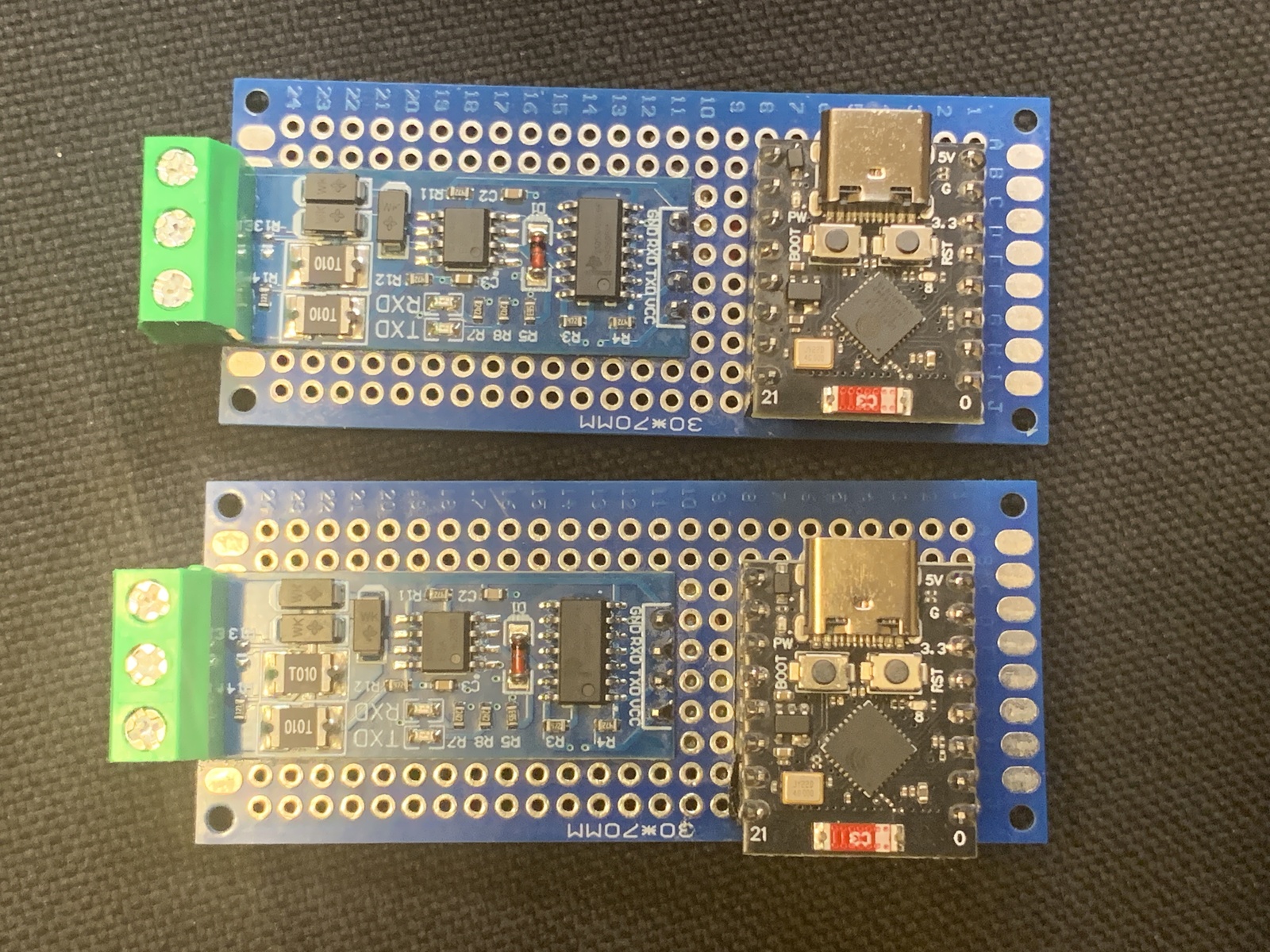
As I’ve been slowly building out our “smart home” system for a couple of years now, I’d been intending to more fully integrate our electrical submeters and hydronic heating boiler into that system, as I knew both systems could communicate over RS485 serial interfaces. About a year ago, I had installed some Elfin EW-11 RS485-to-WiFi converters, so that I could learn how to speak to the submeters and boiler directly over the network, and perhaps integrate them that way.
I was able to familiarize myself with the protocols. However, integrating with the EW-11 converters would require running another program on a server on the network to handle all of the protocol conversion into something Home Assistant could work with. I decided that I’d prefer a more elegant solution where the protocol conversion and direct communication to Home Assistant would be handled by the same device that connects to the RS485 bus and WiFi in the first place. And, since the EW-11 is not really designed with that sort of programming in mind, I would need to build something to replace them.
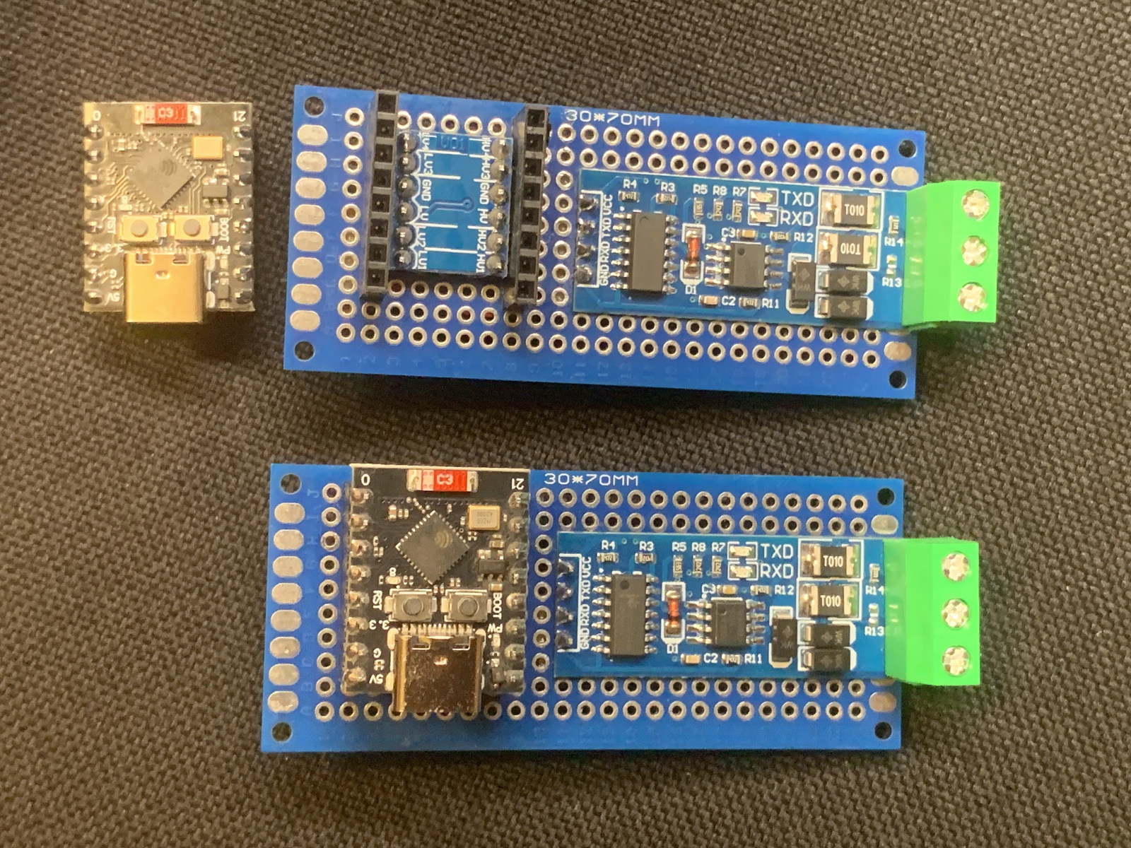
In this end, this would mean building a relatively simple circuit from some off-the-shelf modules, and designing and 3D printing an enclosure for it.
Circuit Notes
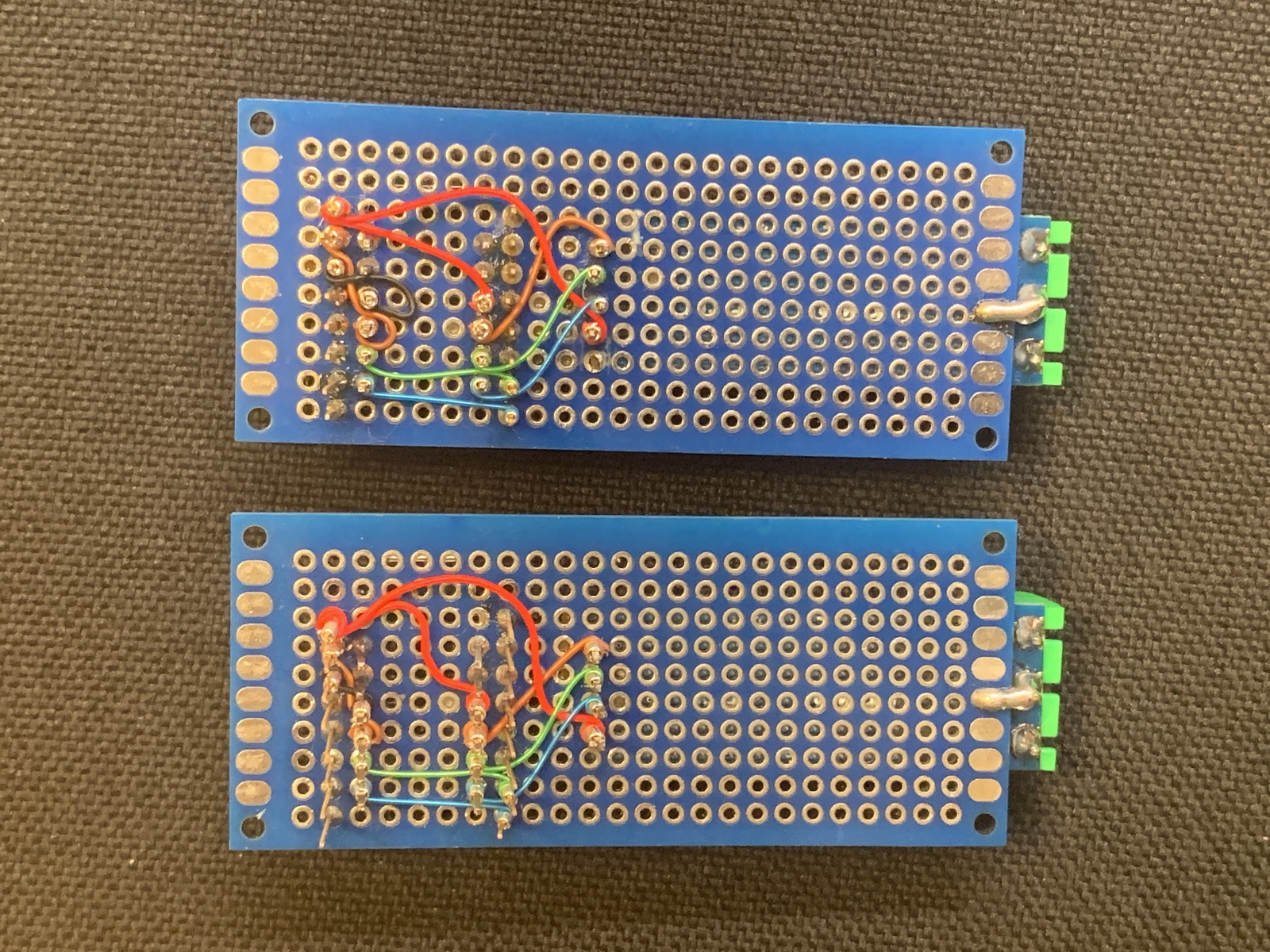
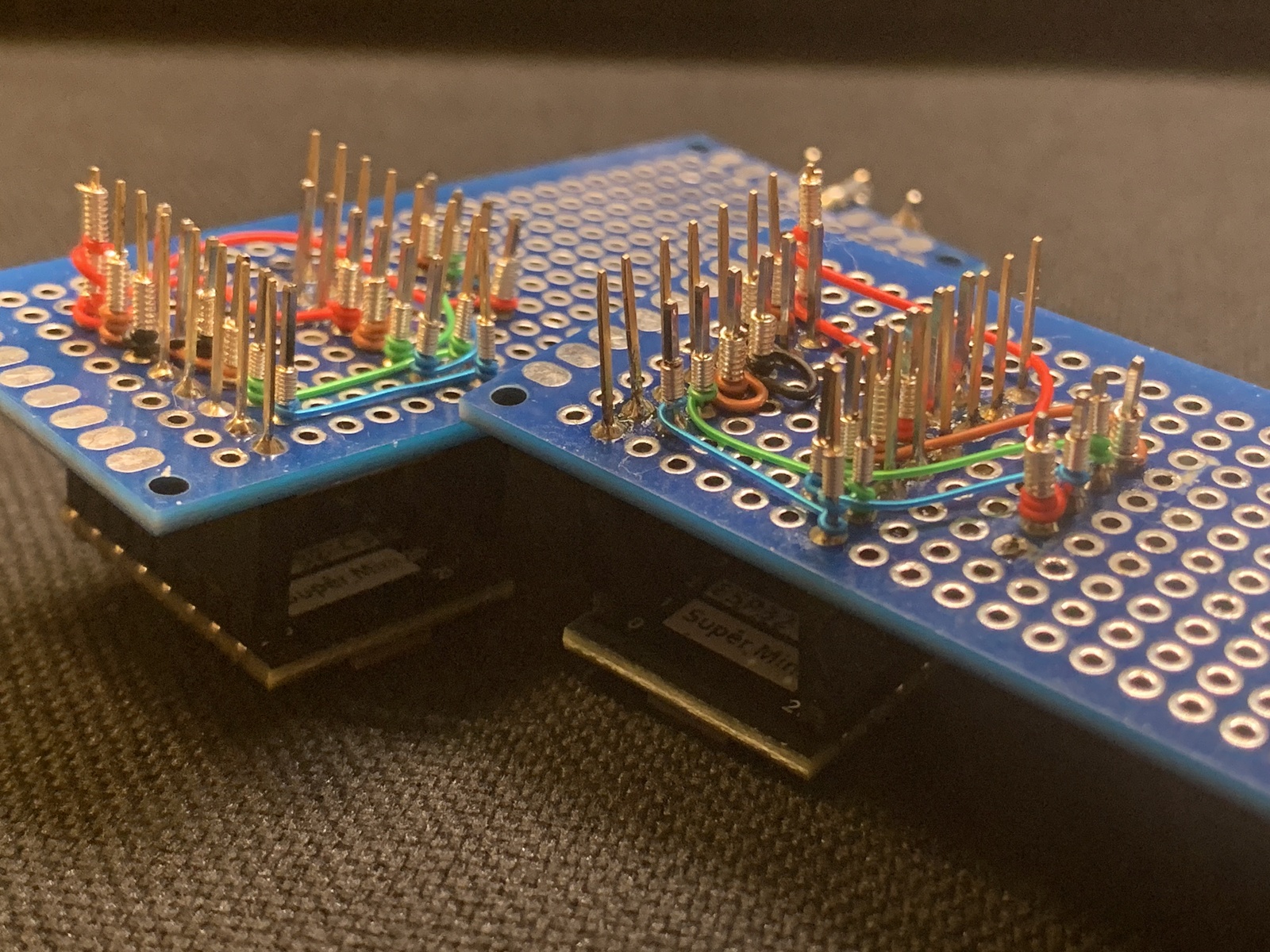
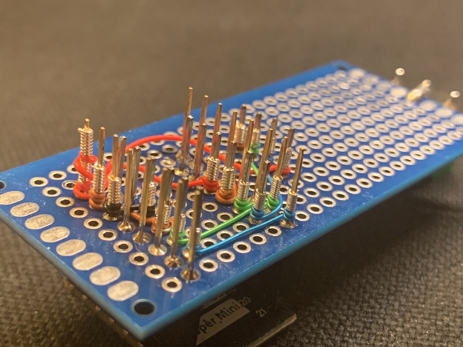
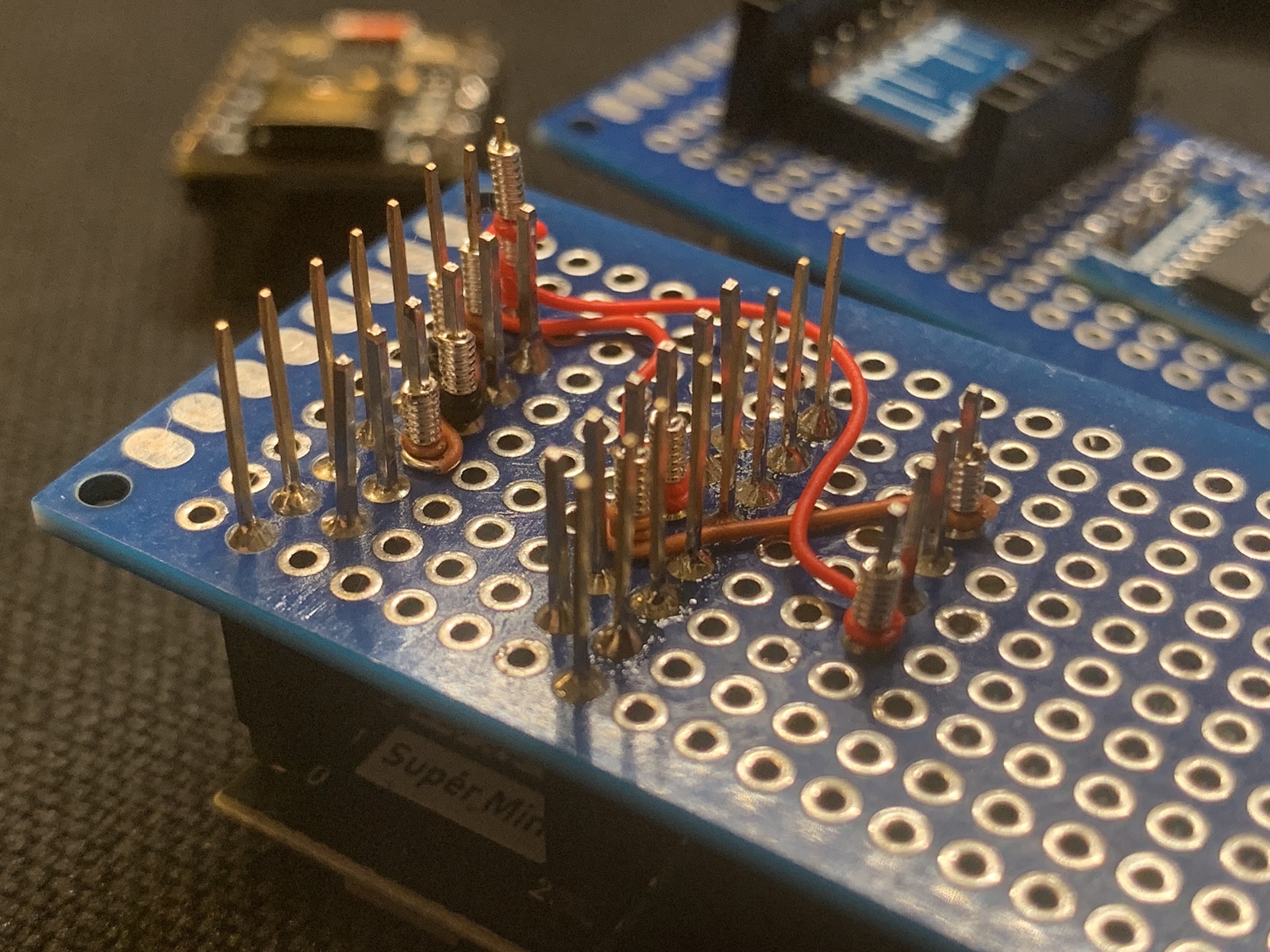
Although I do enjoy soldering as an activity, I don’t like soldering to wires if I can help it. This preference could make creating custom circuits on off-the-shelf prototyping boards very frustrating, as it’s typical to use soldered wires to serve as a substitute for the missing circuit traces. Thankfully, I have collected the tools and materials necessary for wire-wrapping circuits instead.
Wire-wrapping is a great option in most ways, and I love it, but it does leave long and potentially fragile pins exposed, which further necessitates that the final circuit be housed in a protective enclosure.
Enclosure Notes
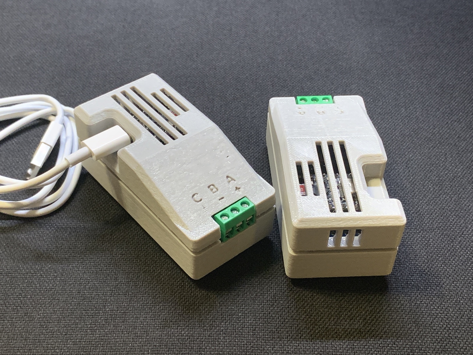
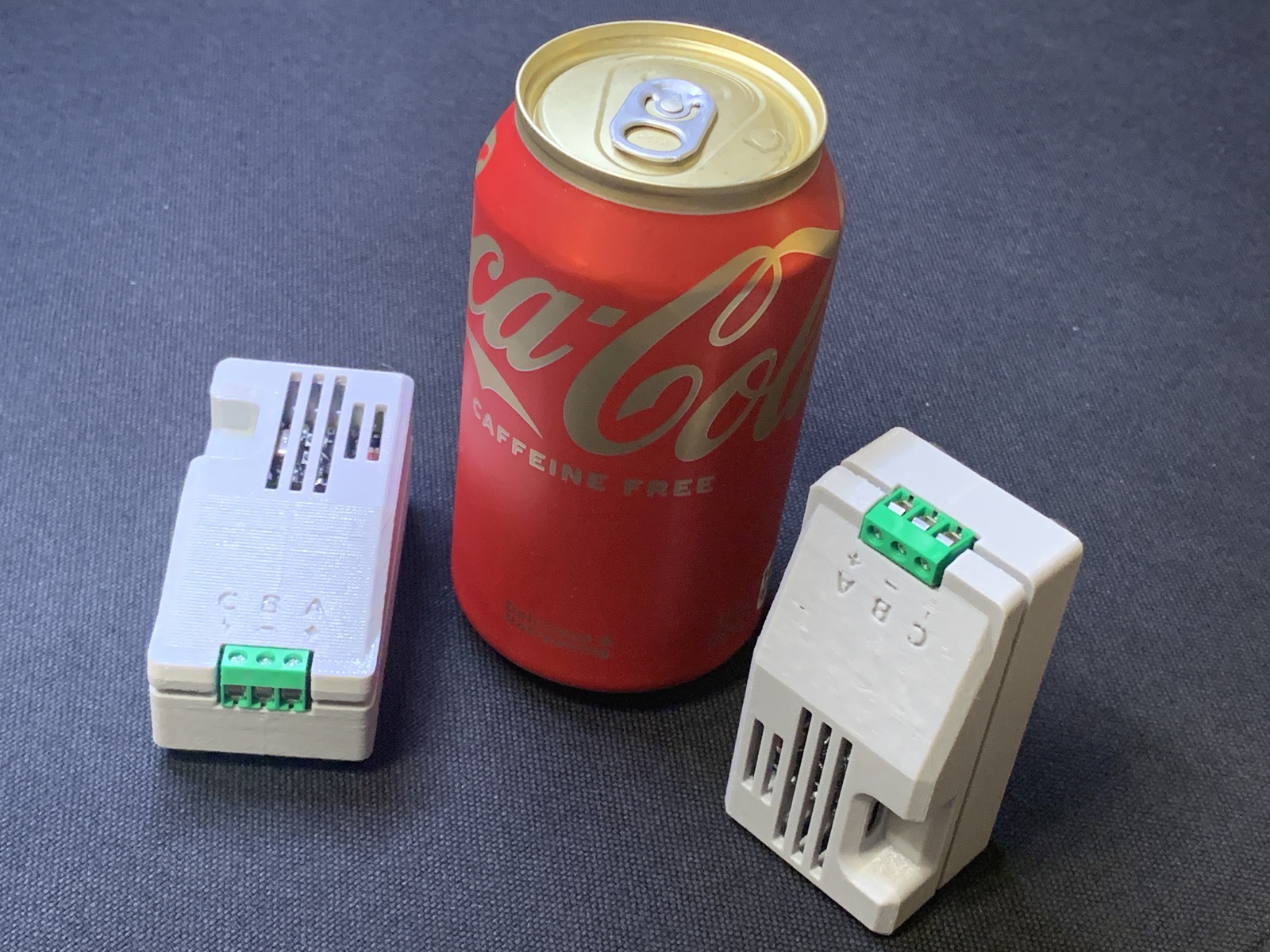
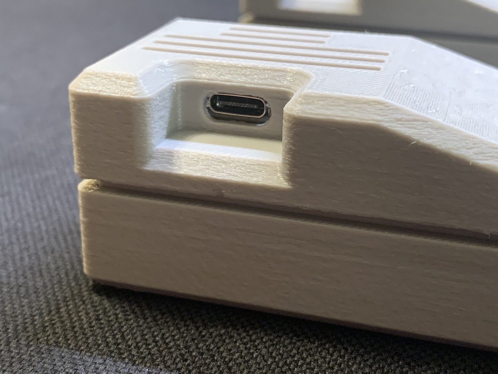
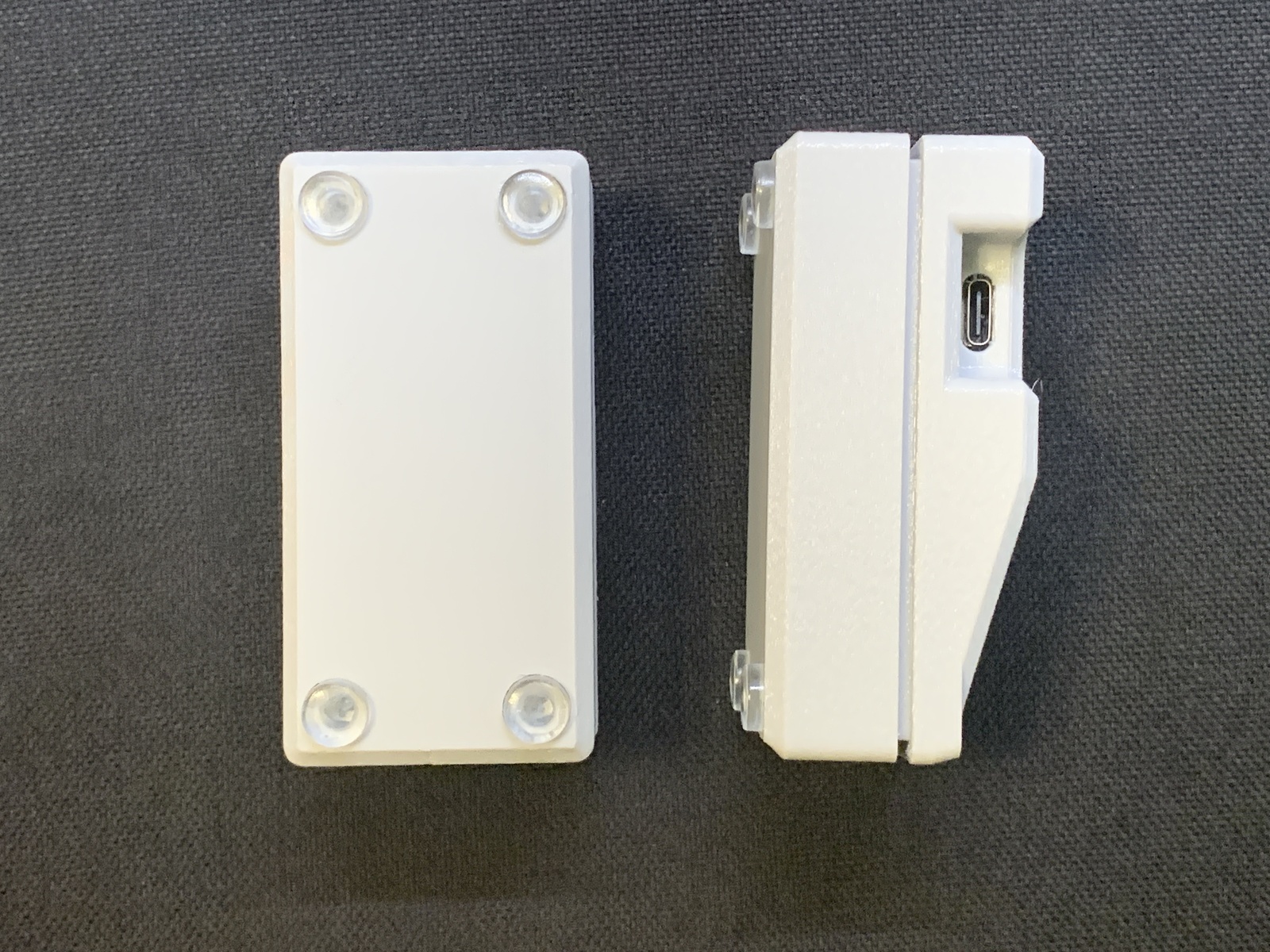
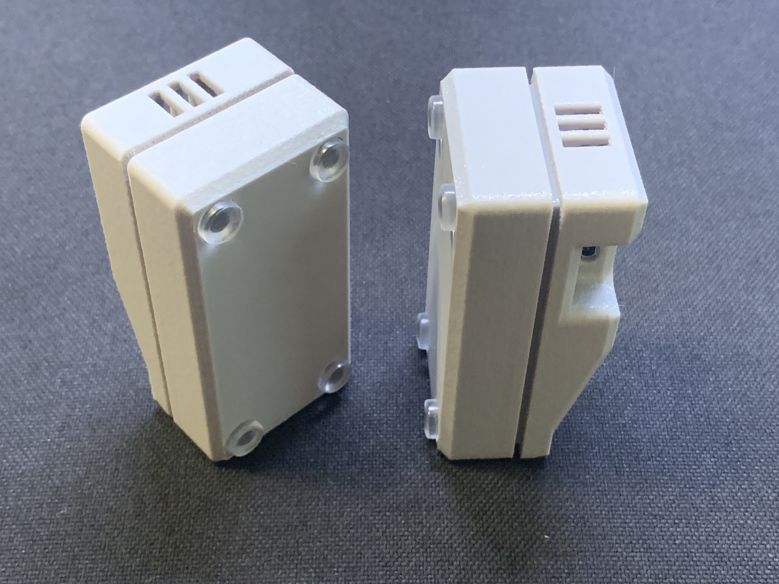
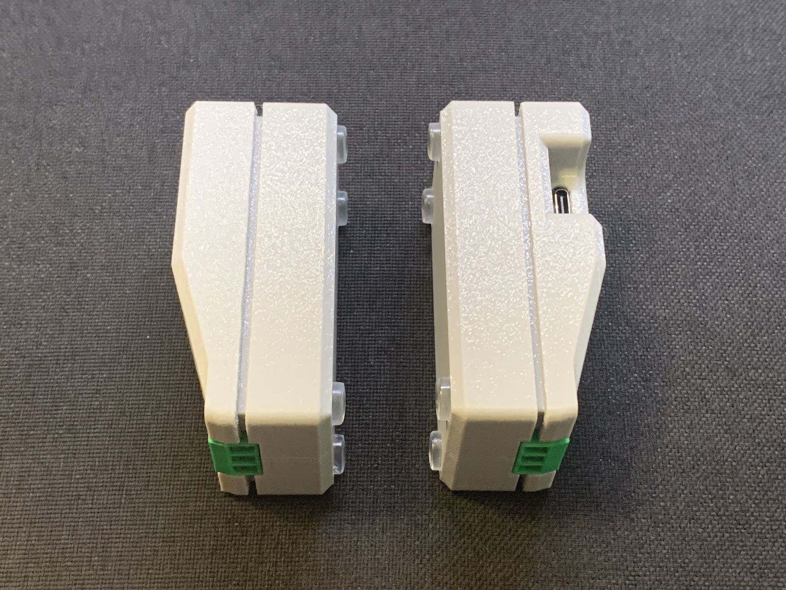
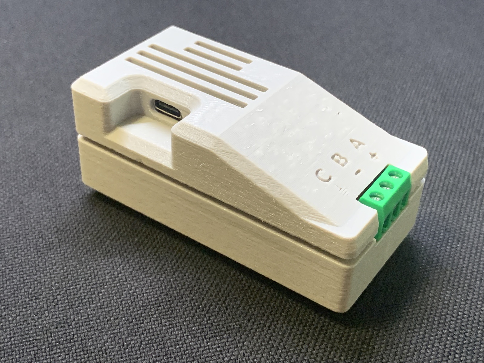
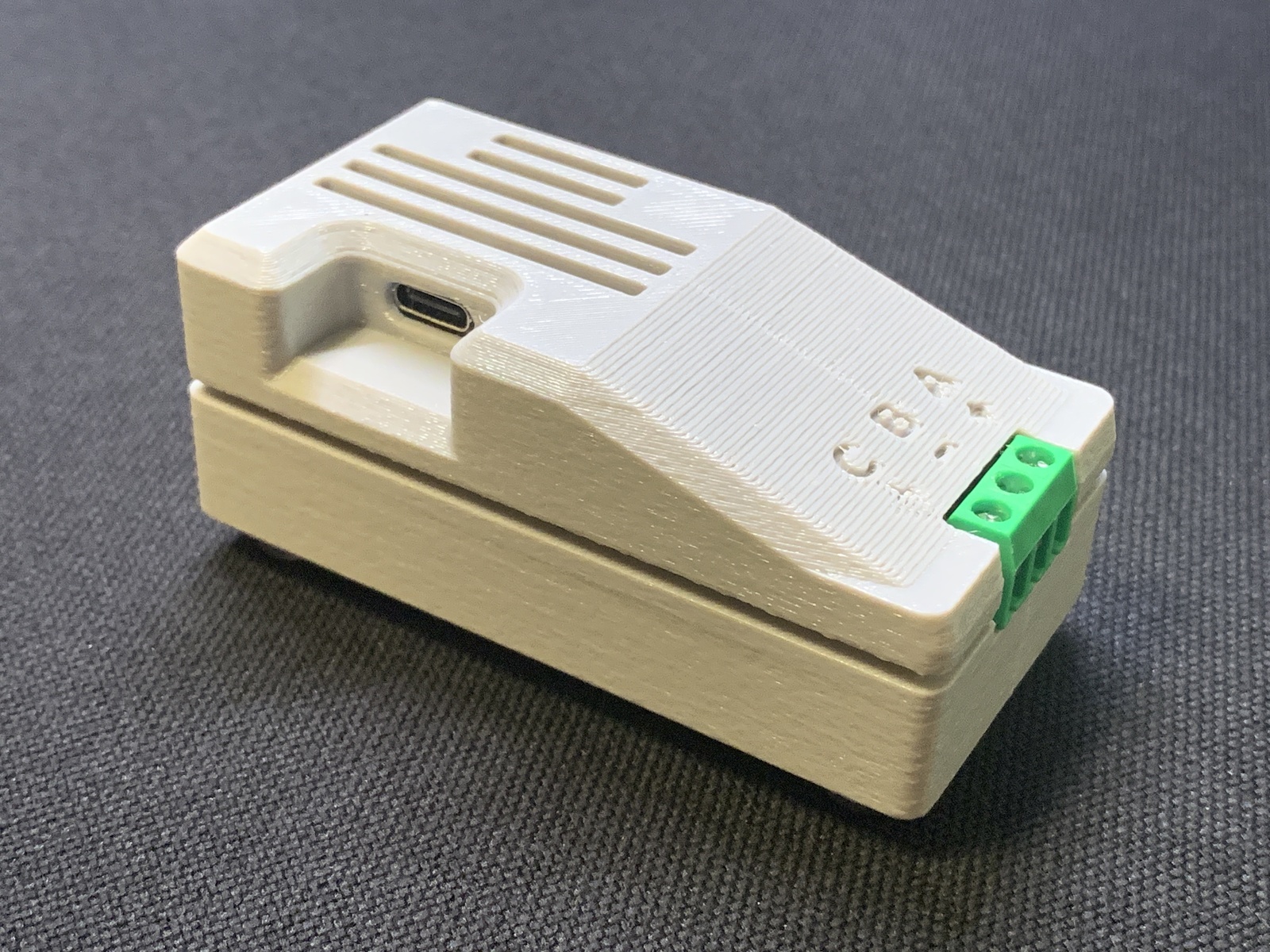
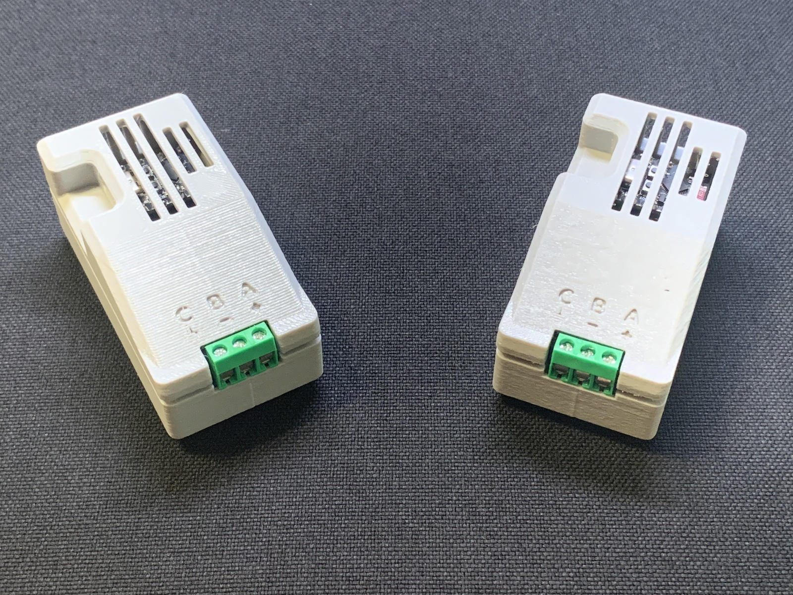
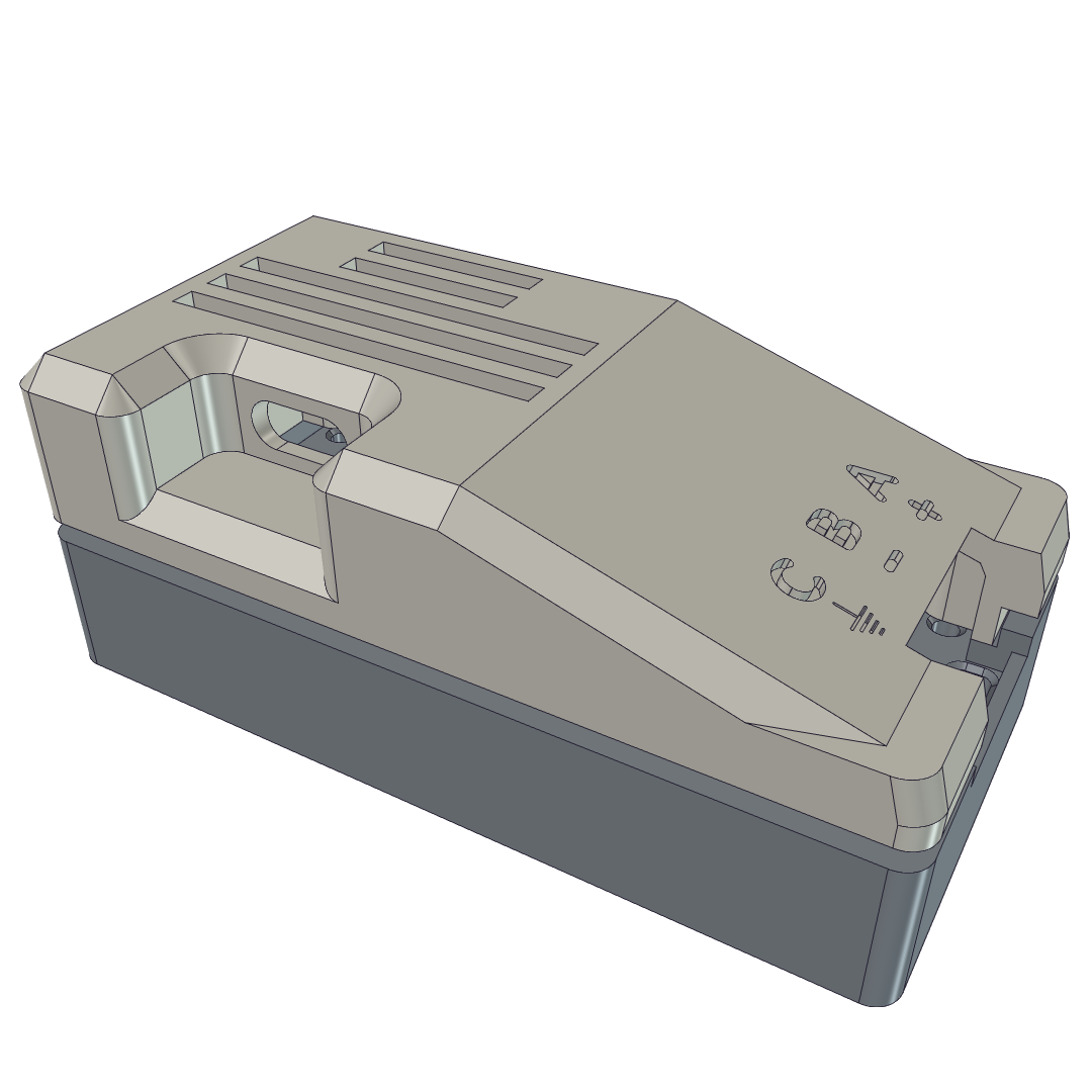
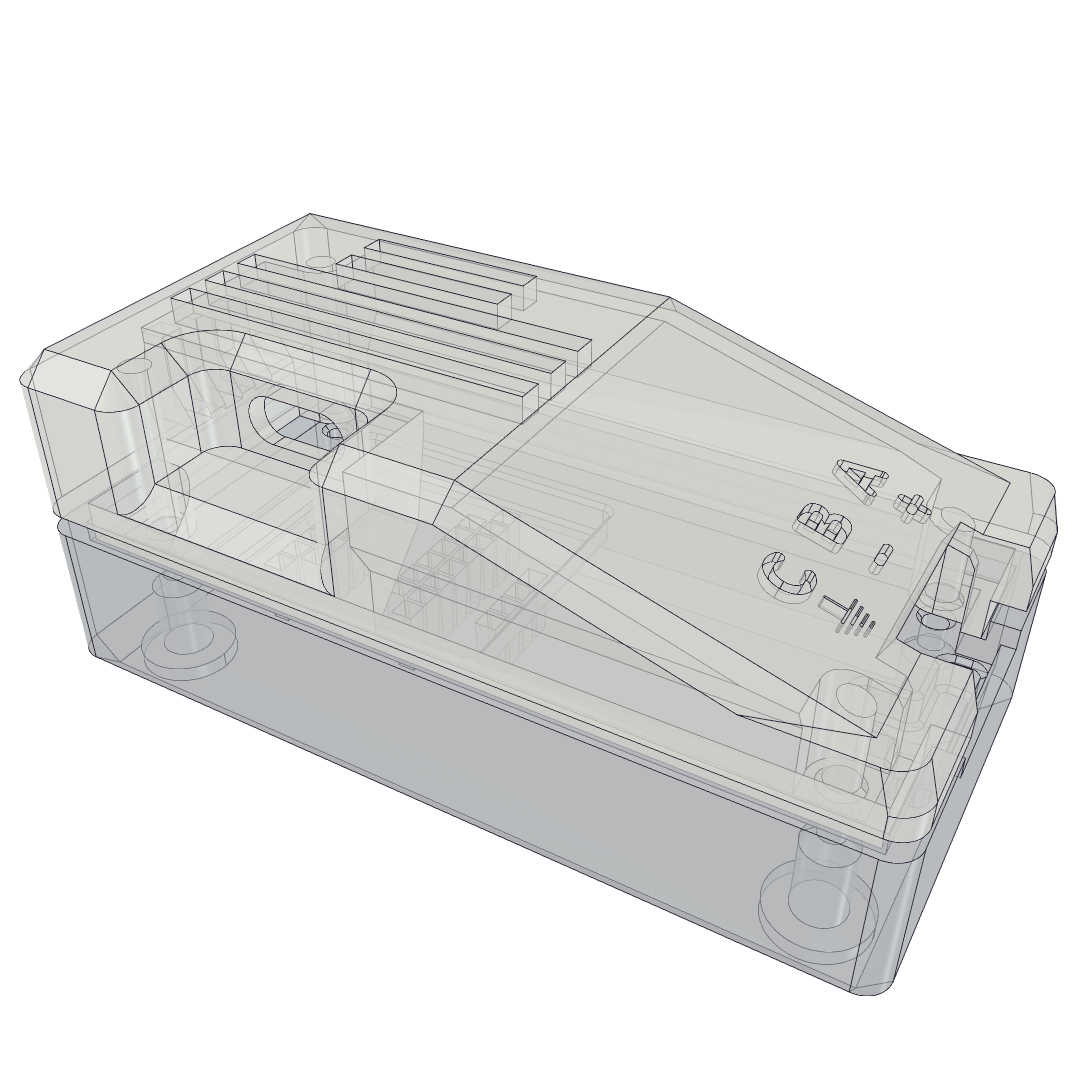
So, that need to protect the pins, as well as the need to expose the USB-C port for powering the microcontroller, and the screw terminals to connect to the RS485 bus, determined the broad shape of the enclosure, but I did try some new things, and attempted to make it look nice, too.
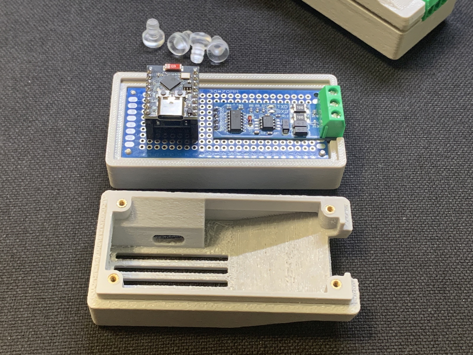
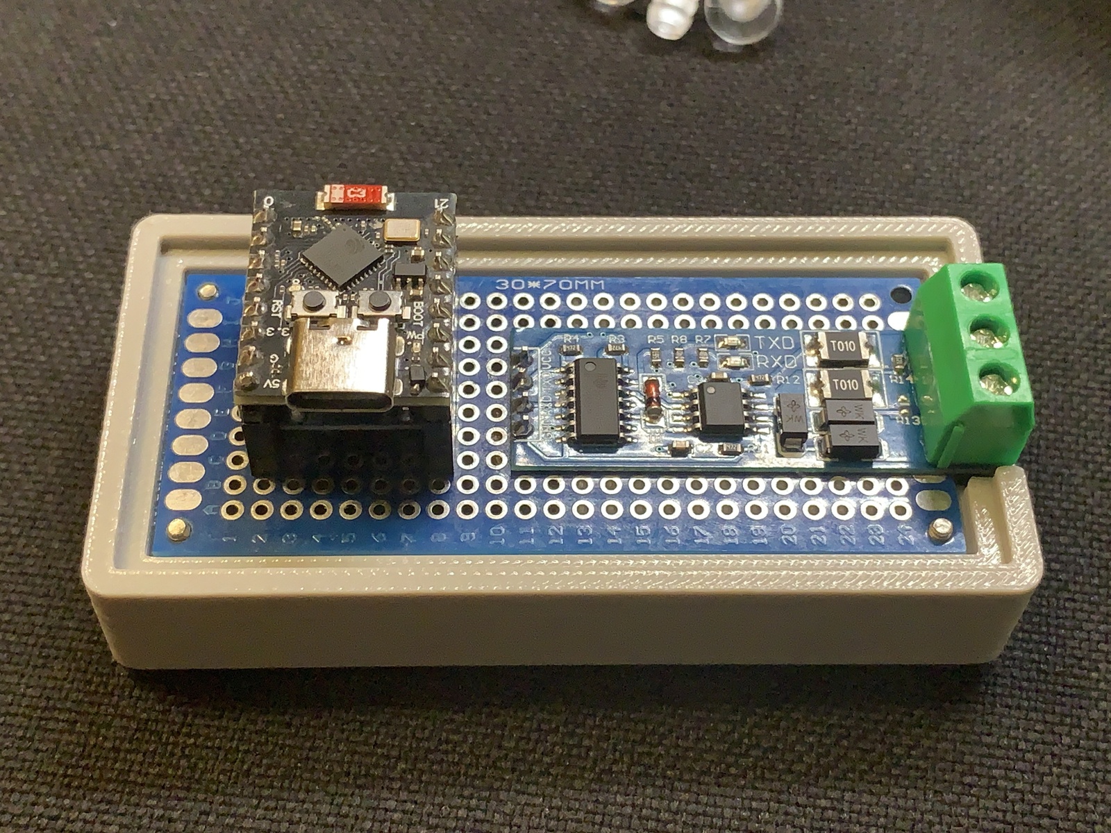
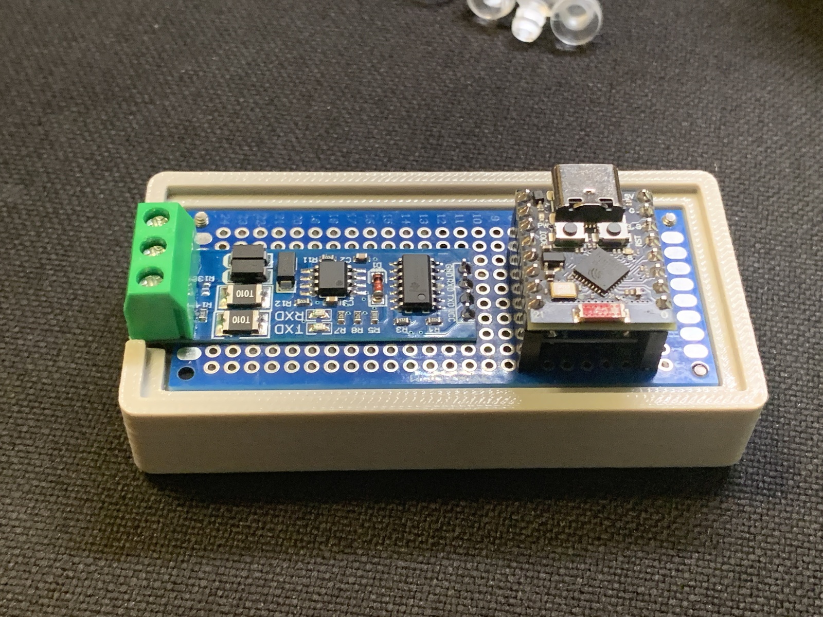
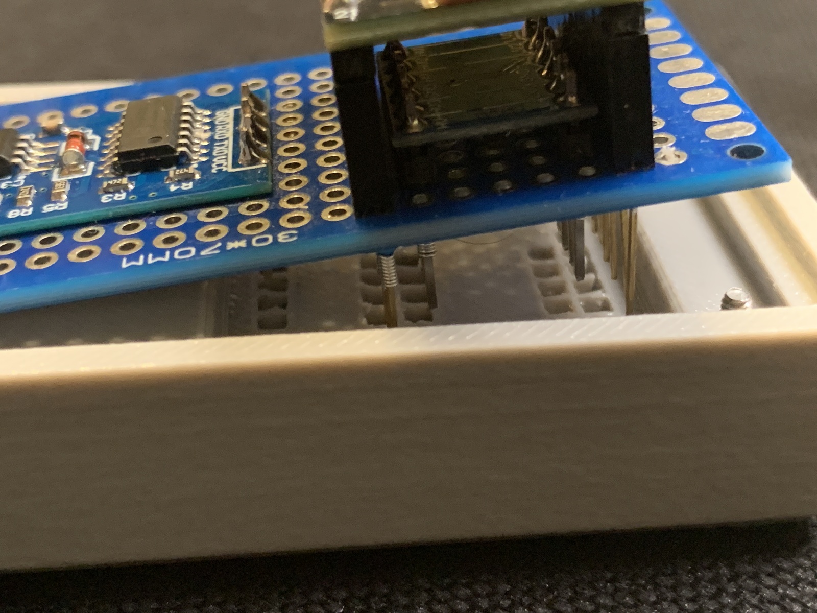
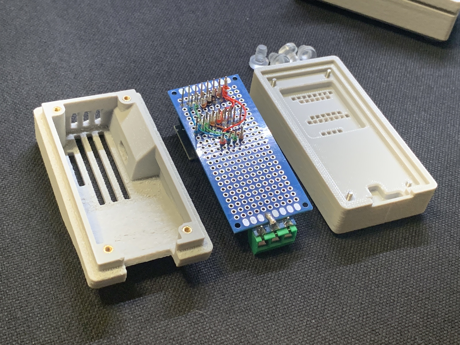
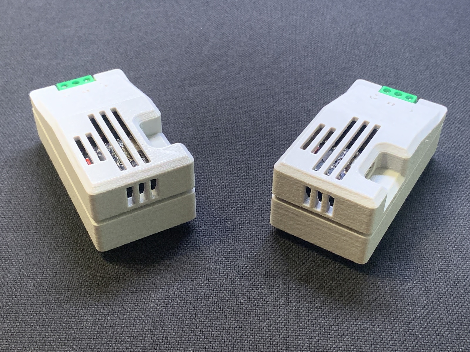
Regarding the pins, I would not be surprised at all if someone had done this before, as it’s pretty obvious, but I’ve never actually seen what I’ve done here with this enclosure before: In addition to the necessary allowance for the layer of connecting wires, I also designed little individual insulating chambers for the long pins to ensure that they can’t be bent into each other and cause a short. I had been imagining this for a while, but I wasn’t sure how well it would work in practice. This was my first time implmenting that approach, and I’m very happy with the result. The final assembly goes together and the pins key in very smoothly and snugly, it’s very satisfying.
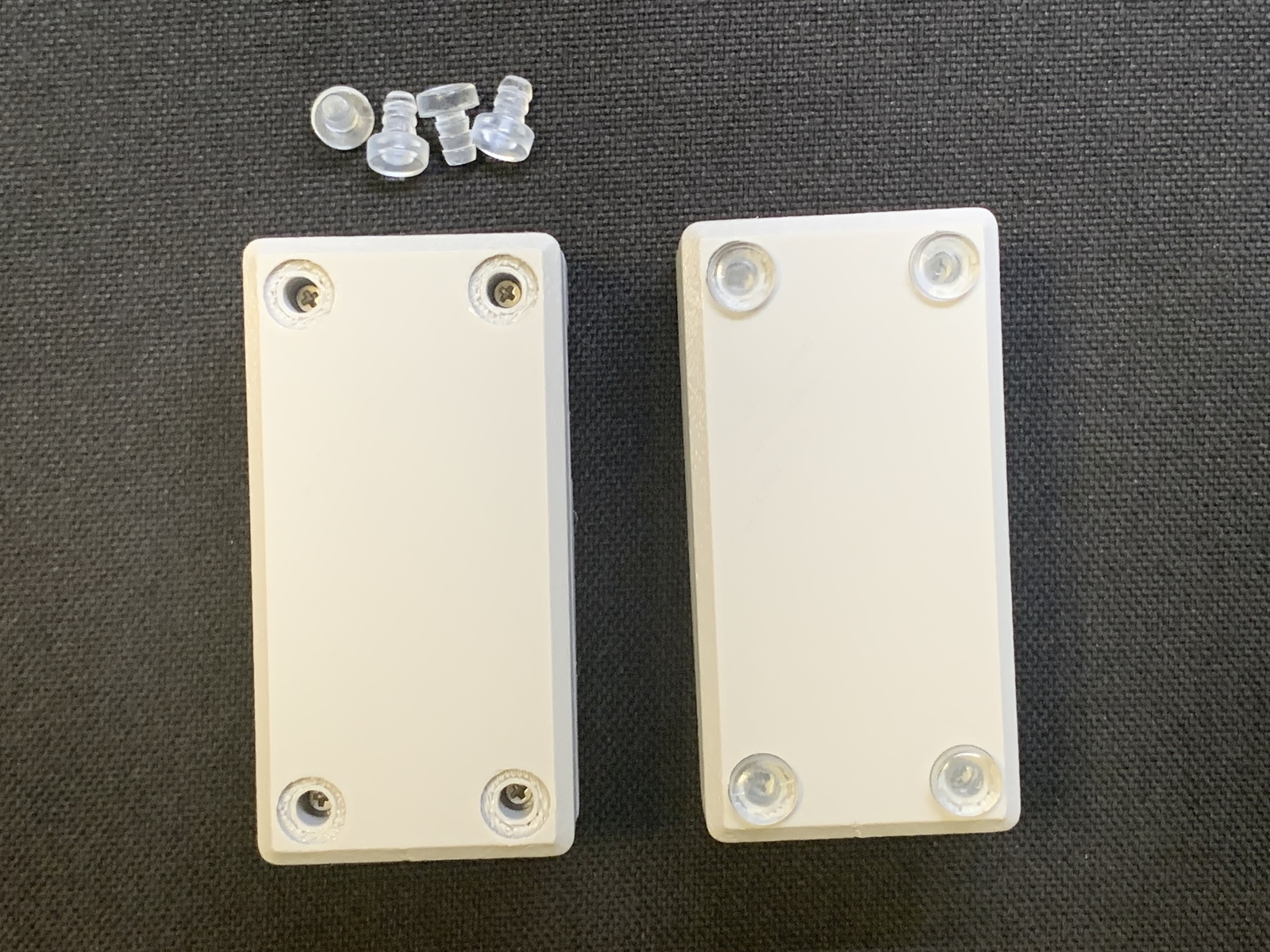
As with my other enclosures (going back to the first enclosure I designed, for a Raspberry Pi 4), I was able to hide the fasteners on the bottom, for a clean look. This time, I used some rubbery plug feet that I found a while ago with the intent to try them with an enclosure project like this, as they both add protective feet and hide the screw holes. They are very secure and reassuringly “click” into place, but they can also be pulled out cleanly with any rigid tool, and reinstalled, many times as needed without any damage. I’ll definitely be using them again in future enclosure designs.
Overall, I’m very happy with the result.
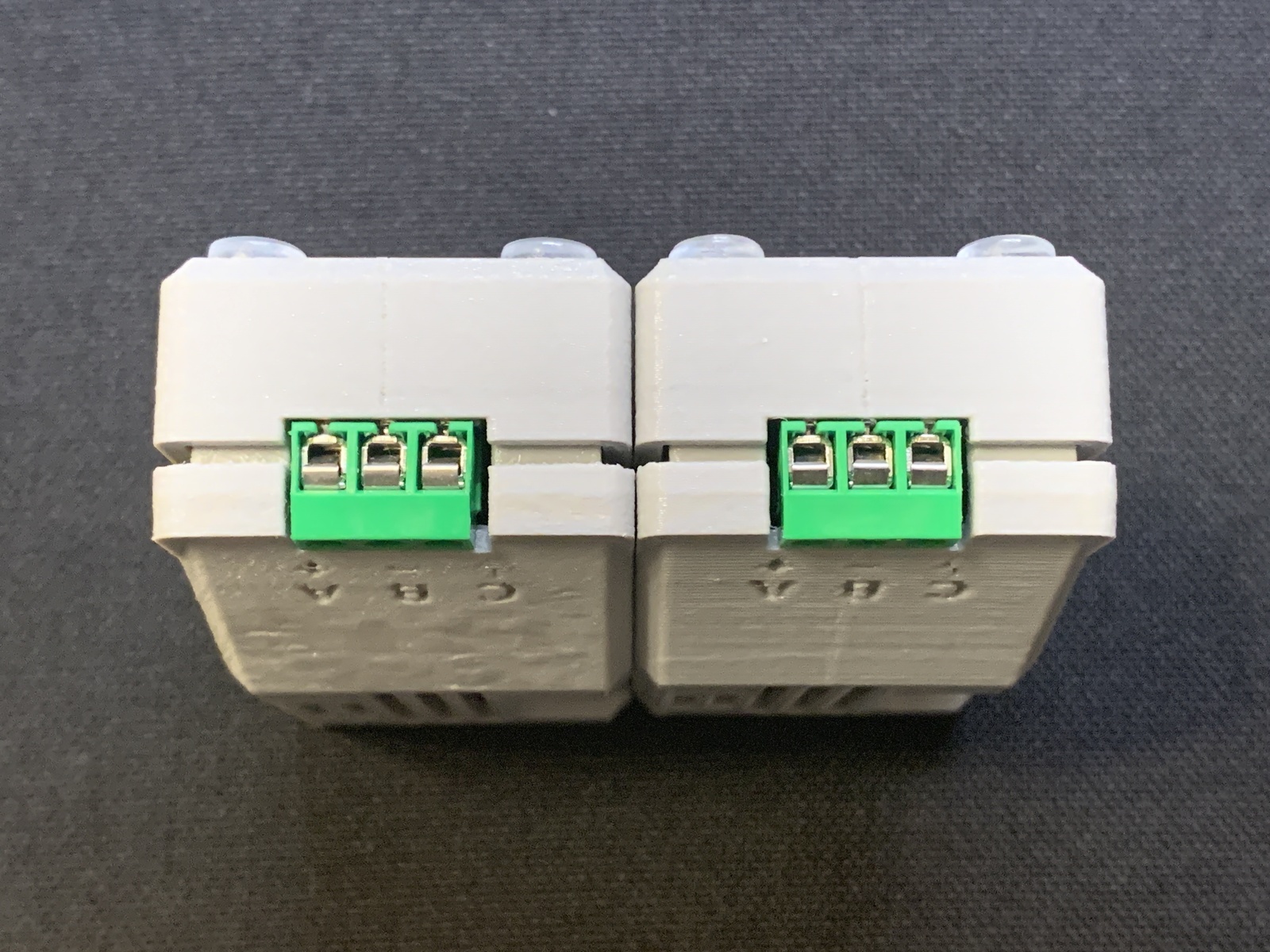
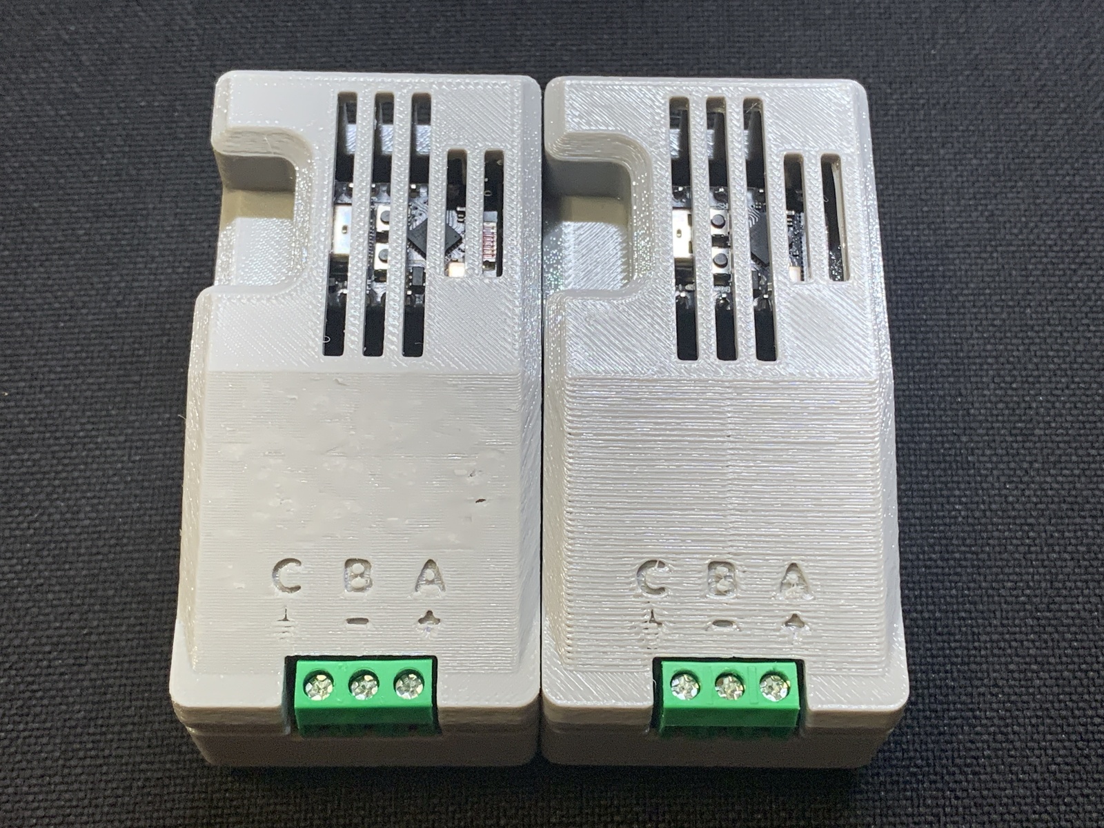
In the photos below, the minor difference you might notice between the two is a result of my comparing both 0.2mm and 0.1mm layer heights when doing the final 3D printing of the lid, to see if the smaller layer size produced a notable improvement. I actually determined that I somewhat prefer the 0.2mm version, in the end, due to the difficulty in dealing with supports and various print artifacts with smaller layers, but it’s not a significant difference.
Enclosure Images
(don’t miss the neat 3D viewer at the bottom!)

Circuit Images